Boiler Service and Maintenance Tips
We have put together some helpful boiler service tips to keep your boiler up and running smoothly.
Maintenance is the single most important thing you can do to increase the life of your boiler.
If you are having trouble with your boiler, please check out our Boiler Service page.
Proper Sizing of Boiler Feedwater System
At some point in time you may wish take your boiler off line and store it for an extended period of time. Be very cautious. Boilers that sit idle will corrode leaving you with a quite a mess when you want to place the boiler back in service.
Here are two ways you can store your boiler.
The first is wet storage, which is generally better for shorter periods of time. In fact, we would recommend wet storage for anybody that needs a boiler for emergency stand-by. A word of caution, make sure the temperatures in your boiler room do not dip below freezing.
For wet storage we recommend the following steps:
- Inspect the boiler and clean it if needed
- Fill the boiler with deaerated feedwater to the normal levels
- Contact your water treatment company for the chemicals needed to condition the water
- An alternative would be using a nitrogen blanket throughout the entire boiler. Make sure the vents are closed and that the nitrogen pressure is greater than atmospheric pressure.
The dry storage method is preferred for boilers that will be out of service for an extended period of time or where the temperatures can go below freezing.
- Again, inspect and clean your boiler
- Drain all the water and make sure that the boiler is completely dried. Remember, any moisture left on boiler surfaces will eventually corrode
- Next make sure that moisture cannot enter the boiler. Close off any steam lines, feed lines and any points of entry for air
- Then place moisture absorbent material, such as quicklime or silica gel inside the boiler. This should be placed on trays inside the boiler. We suggest 2 pounds of quicklime or 5 pounds of silica gel per 30 cubic feet of boiler volume.
- Close up all manways and handholes
- Next place a sign on the boiler so that nobody makes the mistake of firing it without removing the absorbent material. This sign might read as follows:
Attention – moisture absorbent material has been placed in the water side and furnace of this boiler. This material must be removed before water is placed in the boiler and before the boiler is fired. - Finally, inspect the boiler every two or three months and replace the absorbent materials with new or regenerated materials.

Since water is the key ingredient used in a boiler system, it is important to understand just exactly what is in the water you will be using. We recommend that customers have a water analysis performed so they have a true picture of what they are dealing with.
One of items that will be quantified in the analysis is the hardness. This is really the amount of mineral contamination that is found in your water. This degree of contamination can be measured by either a chemical analysis or by measuring the water’s ability to conduct (or resist) an electrical current.
Hardness can be reported in one of three different expressions:
- Mg/l – milligrams per liter
- Ppm – parts per million
- Gpg – grains per gallon
We normally work with the grains per gallon expression as it is the easiest for all to understand. Imagine if you took a pill that weighed 8 grains and dissolved it in 1 gallon of pure water. The result would be 8 grains per gallon. Simple and easy to understand, however, other like to express water hardness as mg/l or ppm. Here is a table that can help you make the conversion:
- Gpg X 17.1 = ppm
- Gpg X 17.1 = mg/l
- Ppm X .05833 = gpg
- Mg/l divided by 17.1 = gpg
Water hardness becomes an issue as soon as heat is applied in the boiler system. The most common problem is that of scale formation, a problem that will rob your system of the efficiency it was designed to deliver.
The following formula demonstrates scale formation.
To protect your boiler system, invest in an ion exchange water softener.
Buying a packaged boiler is kind of like buying a new car. You need something that will get the job done within a given price range.
There are some features that you must have and others that you would like to include if it fits that budget. Style counts for a lot in the purchase of a car; not a real critical factor in the boiler world.
Whether your boiler is to be used for process duty or for heating purposes there are some basic points that you must consider. This listing was adapted from HVAC Systems and Components Handbook edited by Nils R. Grimm and Robert C. Rosaler. (McGraw-Hill Companies, 1998)
We have included some additional points that we believe should also require careful consideration.
- Just exactly what do you want the boiler to produce? Low Pressure Steam, High Pressure Steam, Hot Water, High Temperature Hot Water.
- How big a boiler do you need? How much steam or hot water is required to satisfy your needs?
- What duty will the boiler serve? Will it be used for space heating, process steam, humidification or any other number of duties?
- How critical is it to have the boiler on-line? If it were extremely critical it would be advisable to have built in redundancy included in your plans.
- How about the type of fuel you have available? Natural Gas, Fuel oil (no. 2, 4 or 6) Propane, Coal, Wood or a combination of fuels. What is readily available and what is economical for your application?
- What type of combustion air system would you like? Forced draft systems are inherently more efficient and also more expensive than the atmospheric burners. Outside influences such as emission controls, boiler location and space availability will all contribute to this selection.
- How will you vent the boiler and how will you bring in fresh combustion air? These are two key points that will influence your burner selection. You may wish to consider including an Exhausto fan assist system in your design.
- Who will take care of the boiler after it has been installed? After sale support is a critical factor to consider. This includes the availability and price of aftermarket parts.
Get Ready! The time is fast approaching when you will need to have your boilers back on-line. Yes, winter is coming and so are the demands placed upon your boilers.
To make sure you are operating safely and at peak efficiency we recommend that you, or a qualified boiler service technician, open your boiler for an inspection. Clean both the fireside and waterside. If you haven’t had your boiler inspector out, call him so that he can take a look.
When you reassemble your boiler use new gaskets. Also clean and inspect your low water cutoff. Check all safety devices, including a pop test on the safety relief valves, flame safeguard checks and a leak test on safety shut-off valves.
Here is a checklist of items to inspect, clean, repair or replace as required:
- All refractory
- Replace all fireside gaskets
- Refractory baffle gaskets
- Burner gaskets
- Handhole gaskets
- Manhole gaskets
- Low water cut-offs
- Oil gun assembly
- Pilot electrode and pilot tube
- Flame detector
- Scanner tube
- Programmer
- Damper motor
- Cam assemblies
- Linkages
- Ignition transformer
- Ignition cable
- Operating limit controls
- Pilot Valves
- Main gas valves
- Main gas regulator
- Gas butterfly valve
- Blower motor
- Air proving switch
- Atomizing air pump
- Air cleaner
- Strainers
- Air and oil hoses
- Oil valves
- Oil metering stem
- Back pressure orifice
- Stem packing
- Gauges
- Stack thermometer
- Water column assembly
- Tyrcocks
- Safety Valves
- Sight ports
Boilers come in many different sizes, shapes and designs.
This creates quite a challenge for those of us that do not purchase boilers on a regular basis. The choice between a firetube design and a water tube design can become very confusing for novice boiler buyers. We thought a quick discussion on the advantages and disadvantages of these boiler designs might prove helpful.
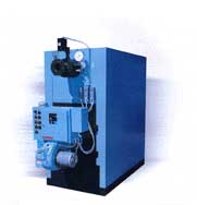
FIRETUBE BOILERS
The Hurst LPE “Performance” boiler is America’s most heavily designed and built boiler in its class.
A welded steel firetube boiler, the LPE has extra heavy 12 gauge tubes for extended life. All tubes are attached to the tube sheets by rolling and flaring. There are no welded tubes in the LPE.
Thickest materials used in the industry…
- Boiler shell is 5/16″ thick boiler plate.
- Twin boiler tube sheets are 1/2″ thick boiler plate.
- Insulation is 2″ mineral wool and is lagged with 22 gauge boiler jacket.
- Extra heavy 3″ channel iron boiler skids.
Designed to last with special industrial grade features…
- Couplings are 3,000 psi.
- Flanged, detachable front and rear smoke boxes.
So What is a Firetube Boiler?
The name firetube is very descriptive. The fire, or hot flue gases from the burner, is channeled through tubes that are surrounded by the fluid to be heated. The body of the boiler is the pressure vessel and contains the fluid. In most cases this fluid is water that will be circulated for heating purposes or converted to steam for process use.
Every set of tubes that the flue gas travels through, before it makes a turn, is considered a “pass”. So a three-pass boiler will have three sets of tubes with the stack outlet located on the rear of the boiler. A 4-pass will have four sets and the stack outlet at the front.
Firetube Boilers are:
- Relatively inexpensive
- Easy to clean
- Compact in size
- Available in sizes from 600,000 btu/hr to 50,000,000 btu/hr
- Easy to replace tubes
- Well suited for space heating and industrial process applications
Disadvantages of Firetube Boilers include:
- Not suitable for high pressure applications 250 psig and above
- Limitation for high capacity steam generation
WATERTUBE BOILERS
Unilux Series “Z” Water Boilers:
Provide 85% efficiency to your customers! The unilux series “Z” boilers are available from 20 BHP to 1500 BHP as cataloged standard with larger sizes available by request. This unique, modern forced draft design is the ultimate in water boiler technology. Available as factory packaged or field erect (FE). 20 year warranty on vessel as standard.
What is a Watertube?
A Watertube design is the exact opposite of a fire tube. Here the water flows through the tubes and are incased in a furnace in which the burner fires into. These tubes are connected to a steam drum and a mud drum. The water is heated and steam is produced in the upper drum. Large steam users are better suited for the Water tube design. The industrial watertube boiler typically produces steam or hot water primarily for industrial process applications, and is used less frequently for heating applications.
Watertube Boilers are:
- Available in sizes that are far greater than the firetube design. Up to several million pounds per hour of steam.
- Able to handle higher pressures up to 5,000 psig
- Recover faster than their firetube cousin
- Have the ability to reach very high temperatures
Disadvantages of the Watertube design include:
- High initial capital cost
- Cleaning is more difficult due to the design
- No commonality between tubes
- Physical size may be an issue
Refer to the following table for recommended boiler water quality for Total Dissolved Solids (TDS), Alkalinity and Hardness.
Proper Feedwater Treatment is an absolute necessity!
Unless your boiler receives water of proper quality, the boiler’s life will be needlessly shortened. A steam plant’s water supply may originate from rivers, ponds, under ground wells, etc. Each water supply source requires a specific analysis. Depending upon this analysis, various pretreatment methods may be employed to prepare makeup water for your boiler feedwater system.
General Information on Water Treatment
Suspended solids represent the undissolved matter in water, including dirt, silt, biological growth, vegetation, and insoluble organic matter.
When minerals dissolve in water, ions are formed. The sum of all minerals or ions in the water in the Total Dissolved Solids (TDS).
Iron can be soluble or insoluble. Insoluble iron can clog valves and strainers and can cause excessive sludge build up in low lying areas of a water system. It also leads to boiler deposits that can cause tube failure. Soluble iron can interfere in many processes, such as printing or the dying of cloth. In domestic water systems, porcelain fixtures can be stained by as little as 0.25 ppm of iron.
Water Hardness is the measure of calcium and magnesium content as calcium carbonate equivalents. Water Hardness is the primary source of scale in boiler equipment.
Silica in boiler feedwater can also cause hard dense scale with a high resistance to heat transfer.
Alkalinity is a measure of the capacity of water to neutralize strong acid. In natural waters, the capacity is attributable to bases, such as bicarbonates, carbonates, and hydroxides; as well as silicates, borates, ammonia, phosphates, and organic bases. These bases, especially bicarbonates and carbonates, break down to form carbon dioxide in steam, which is a major factor in the corrosion of condensate lines. Alkalinity also contributes to foaming and carryover in boilers.
The costs associated with these boiler repairs are typically high both in labor, much of which is done on an overtime basis, and the associated downtime. By far this is the least desirable approach to boiler maintenance.
A proactive maintenance program pays dividends in not only peak boiler performance but also in the overall safety of those working in the boiler plant.
On the other end of the boiler maintenance spectrum is a proactive maintenance program.
This type of maintenance approach uses scientific testing techniques and analysis to anticipate and correct, by either repair or replacement, problems before they arise. Real time monitoring has contributed greatly to the ability to view and respond to changes in boiler operation and overall process performance. Operators can compare past baseline results against current readings to determine if a problem may be forth coming.
The key to properly analyzing boiler room conditions is having accurate data available. Boiler room logs are an important part of this process. Critical predetermined readings, such as fuel consumption and flue gas temperatures, are recorded on a daily or even a per shift basis. These recorded readings then give the operator a base line to compare present readings against. As an example, if the flue gas temperature of a boiler has gradually increased over the course of a month the operator will be able to evaluate the system. He might then determine that there has been a build up of scale reducing heat transfer.
Keep in mind that every boiler operation is different. Some will require more extensive logs as opposed to others. This is an area that management and boiler operators must review and jointly decide upon.
Following is a suggested list of points that we feel require daily recordings:
- Water Level
- Low Water Cut Off Tested
- Blowdown Water Column
- Blowdown Boiler
- Visual check of Combustion
- Boiler Operating Pressure/Temperature
- Feedwater Pressure/Temperature
- Condensate Temperature
- Feedwater Pump Operation
- Flue Gas Temperature
- Gas Pressure
- Oil Pressure and Temperature
- General Boiler/Burner Operation
A Check List for Planned Preventive Maintenance
P. C. McKenzie Company offers planned preventive maintenance services for a number of industrial and commercial boiler installations. Although each installation is unique there are some common maintenance steps that our service group follows.
Even though not all of these steps apply to every boiler design, we thought they might prove helpful in designing a planned preventive maintenance check list for your facility.
- Open front and rear doors. Clean and vacuum fireside surfaces as required.
- Inspect all refractory. Patch and wash coat as required.
- Inspect all gasketing on front and rear doors and replace as necessary.
- Seal and close front and rear doors properly.
- Remove low and auxiliary low water cut off controls, clean and inspect. Then re-install using new gaskets.
- Remove plugs in control piping, inspect, clean and re-install.
- Remove all hand hole and man hole plates. Flush boiler with water to remove loose scaled and sediment.
- Replace all hand hole and man hole plates with new gaskets.
- Open feedwater tank manway, inspect and clean as required. Replace manway plate with new gasket.
- Clean burner and burner pilot.
- Check pilot electrode and adjust or replace.
- Clean air damper and blower assembly.
- Clean motor starter contacts and check operation.
- Make necessary adjustments to burner for proper combustion and record all results in service report.
- Perform all flame safeguard and safety trip checks and record results in service report.
- Check all hand hole plates and man hole plates for leaks at normal operating temperatures and pressures.
- Troubleshoot any boiler system problems as requested by on-site personnel.
There are two sides to every firetube boiler and we don’t mean the inside and outside of the boiler. We are really referring to the Water Side and the Fire Side of the boiler. Both require inspection and the appropriate maintenance in order to keep your equipment running at peak efficiency.
A visual inspection should be conducted twice a year
The fireside of your boiler will include all refractories, tubes, tube sheets and the furnace. A visual inspection should be conducted twice a year to determine the condition of this side of the boiler heat exchanger. Open the boiler up and use a strong light to visually inspect the condition of these surfaces.
Do you see any blistering or pock marks? This is an indication that there is corrosion due to condensation of flue gasses. This condensation creates an acidic solution that can eat away at your furnace and tubes. Should you find this occurring you may correct the situation by maintaining a minimum water temperature of 170 deg. F. Another solution is to keep your boiler on for a longer period of time. This avoids short cycling that, which allows for the formation of condensation.
If you run a properly adjusted boiler you may only need to clean your tubes once a year.
Next take a close look at the boiler tubes keeping an eye out for soot deposits. Soot is a byproduct of combustion and can seriously reduce heat transfer in your boiler. Poor heat transfer means poor efficiency. If there is soot present make arrangements to have the unit cleaned. How often you clean the tubes will be determined by how you run your boiler. If you run a properly adjusted boiler you may only need to clean your tubes once a year.
If you are experiencing heavy sooting it could be an indication that you are trying to fire too much fuel. Have your burner adjusted by a qualified boiler technician.
Another way to check on sooting is to install a stack thermometer. When the stack temperature rises above normal operating conditions you can be fairly certain it is time to clean the tubes.
While you have your boiler open take a look at the tube sheet. Look for any evidence of leaking tube ends. You can pin point these by a whitish deposit that streaks down from the tube end. If you find this occurring, contact a boiler service company that can re-roll your tubes.
Also check the gaskets used to seal the boiler up. If they are at all suspect, replace them. It is easier to do this now than later when you are firing the boiler.
The last item to check on the fireside is the refractory. Make sure it is all tight and repair any cracks that may have appeared. Use a wash coat to seal these up. If you find any loose refractory brick replace it.
There are some basic pieces of boiler room support equipment that should be considered for a complete boiler installation. This equipment is designed to protect your boiler from harmful water conditions.
Here are some of the basic pieces and the functions they serve:
CHEMICAL FEED SYSTEM
A chemical feed system is used to “feed” the appropriate amount of chemicals into your system to combat scaling and corrosion. A chemical feed system is comprised of a tank, stand, pump, motor and agitator. The feed system is wired so that it will operate in unison with the boiler feed water system or deaerator. This ensures that the proper amounts of chemicals are being fed on a consistent basis.
WATER SOFTENER SYSTEM
A water softener is used to remove hardness from the boiler make-up water. They are available in a wide range of sizes and configurations. By removing hardness in the water you will protect your boiler from the formation of scale that can rob your boiler of its ability to transfer heat efficiently.
BLOW DOWN SYSTEMS
There are two types of blow down systems. A surface blow down/heat recovery and bottom blow down system. A Bottom Blow Down System is used to forcibly remove sludge and sediment from the bottom of your boiler. This is an intermittent process and is dependent upon the boiler operator to perform. It consists of a tank, stand and aftercooler assembly that is used to temper the water before it is sent to the drain. A surface Blow Down System continually removes dissolved solids from the top level of the boiler water and recovers a great deal of the heat which is then returned used to pre-heat boiler feed water.
DEAERATORS
Deaerators are used to remove non-condensable gases from boiler feed water. This is done by heating and aggressively agitating the incoming make-up water. This process reduces the oxygen content of the water to .005 cc/liter and protects your boiler from oxygen pitting and corrosion.
FEEDWATER SYSTEMS
A feedwater system is used to store and return preconditioned make-up water and hot condensate into your boiler. A feedwater system includes a tank, pumps and a stand. Some Feedwater systems include a steam sparge tube, which is used to pre-heat make-up water. This helps to eliminate some of the oxygen in the make-up water.
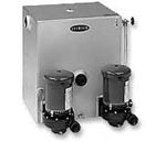
CONDENSATE RETURN UNITS
A condensate return unit is used to reclaim used treated condensate to be used again in your boiler. Not only will you reclaim the water but also the chemicals that were used to treat the water. The result is a significant savings in make-up and the associated chemicals. A Condensate return unit consists of a small tank with small pumps that are used to feed into the boiler.
Blowdown of steam boilers is very often a highly neglected or abused aspect of routine boiler room maintenance.
The purpose of boiler blowdown is to control solids in the boiler water. Blowdown protects boiler surfaces from severe scaling or corrosion problems that can result otherwise.
There are two types of boiler blowdowns – continuous and manual. A continuous blowdown utilizes a calibrated valve and a blowdown tap near the boiler water surface. As the name implies, it continuously takes water from the top of the boiler at a predetermined rate
A continuous blowdown is an optional feature and may not be included on your steam boiler. However, all steam boilers should include a means for manual blowdown as standard equipment.
Manual blowdowns are accomplished through tapings at the bottom of the boiler. These openings allow for the removal of solids that settle at the bottom of the boiler. Manual blowdown is also used to keep water level control devices and cutoffs clean of any solids that would interfere with their operation. All steam boilers require manual blowdown whether or not they are supplied with continuous blowdowns.
Proper blowdown is performed as follows:
Blowdown should be done with the boiler under a light load. Open the blowdown valve nearest the boiler first. This should be a quick opening valve. Crack open the downstream valve until the line is warm. Then open the valve at a steady rate to drop the water level in the sight glass ½ inch. Then close it quickly being sure that the hand wheel is backed off slightly from full close to relieve strain on the valve packing. Close the valve nearest the boiler.
Repeat the above steps if the boiler has a second blowdown tapping. Water columns should be blown down at least once a shift to keep the bowls clean. Care should be taken to prevent low water shutdown if this will affect process load.
NOTE Please keep in mind that all blowdown piping should be checked once a year for obstructions.According to the Refractory Institute:
“Refractories are heat-resistant materials that constitute the linings for high-temperature furnaces and reactors and other processing units. In addition to being resistant to thermal stress and other physical phenomena induced by heat, refractories must also withstand physical wear and corrosion by chemical agents. Refractories are more heat resistant than metals and are required for heating applications above 1000°F (538°C).”
In a boiler the refractory protects the metal surfaces at critical points such as the rear door and in the furnace. This refractory should be inspected periodically to insure protection. Here is a list of what to look for and possible maintenance solutions:
- Visually inspect refractory. Look for large cracks or broken pieces. Small hairline cracks are to be expected.
- Wash coat the refractory with a high temperature bonding, air dry mortar.
- Face all cracks and joints with hi-temp bonding cement.
- If any bricks have fallen out or show signs of excessive wear, replace them.
- Remember, once the repair is complete it is important to follow the manufacturers recommendation for curing the refractory.
We also suggest that you inspect the refractory of your brand new boilers when they arrive on site. Check to be sure that the refractory has not been damaged in shipment. Report any defects to your boiler supplier immediately.
Fan problems can seriously affect combustion efficiency. To fire your boiler at peak efficiency it is necessary to strike the correct balance between fuel and combustion air. These ratios must remain constant throughout the entire firing range so that either fuel-rich or fuel-lean mixtures are avoided.
With an atmospheric burner, air is introduced at the bottom of the burner using natural draft. The fuel/air ratios are then determined by regulating only the gas pressure for the correct mix.
For a full modulating forced or induced draft burner designs, air and fuel ratios are controlled through linkages, fans, dampers and the increase or decrease of gas pressure. As demand is placed on the boiler, the burner will respond by introducing a greater amount of fuel and combustion air. This results in more energy introduced into the heat exchanger.
As a general rule of thumb, it takes about 9.5 cubic feet of air for every one cubic foot of natural gas for ideal combustion to occur. At 10% excess air this ratio will be about 10.5 cubic feet of air to 1 cubic foot of natural gas.
The air and gas must not only be in the correct proportions but also introduced at the proper time to assure complete mixing. Gas pressure is controlled through a pressure regulator and a fan controls the volume of combustion air.
NOTE Here is a list of common fan problems and some possible causes that you may wish to consider.Fan capacity or pressure is below rating:
1. Dampers or variable inlet vanes are not adjusted properly
2. Fan inlet or outlet conditions are impaired
3. Multiple air leaks within the system
4. Damage sustained to the blower wheel
5. Direction of rotation is incorrect
Fan vibrates or makes noise:
1. Worn bearings
2. Unstable foundation
3. Foreign material in the fan causing an imbalance
4. Misalignment of bearings, couplings, wheel or v-belt drive
5. Damaged wheel or motor
6. Bent shaft
7. Worn coupling
8. Loose dampers or variable inlet vanes
9. Speed too high or incorrect fan rotation
10. Vibration to fan transmitted from another source
11. Uneven blade wear
12. Loose or broken bolts or set screws
Overheated Bearings:
1. Improper lubrication
2. Poor alignment
3. Damaged wheel or driver
4. Bent shaft
5. Abnormal end thrust
6. Dirt in bearings
7. Improper belt tension
Overload on Driver:
1. Speed too high
2. Direction of rotation is incorrect
3. Bent shaft
4. Poor alignment
5. Improper lubrication
6. Wheel wedging or binding on fan housing
When people think of a stack system they typically picture a gravity type design; a masonry stack that relays on natural draft to vent the flue gasses. This design is very common in older installations and has been used for centuries. The gravity stack has performed well with the antiquated boiler burner designs of the past but leaves a lot to be desired for today’s high efficiency systems.
Boiler room venting should accommodate:
- Modulating or modular boiler systems with variable heat outputs.
- Long horizontal vents with inadequate rise or capacity.
- Excessive number of turns that create high-pressure loss and inadequate flow.
- Inadequate capacity due to space limitations or the connection of additional equipment to existing systems.
- The need for greater draft or flow than a low-height chimney can provide.
- Erratic or inadequate venting caused by wind, adverse internal pressures, restricted air supply, or indoor/outdoor temperature differences.
- Installation of high efficiency boiler systems to existing chimney system, resulting in the lack of draft and condensation due to lower flue gas temperatures.
The rudimentary mechanical draft assist is a single speed fan that delivers a pre-set volume of air and utilizes a barometric damper for relief should the mechanical draft become too strong. Their design makes them rather inefficient and limits their application to certain types of chimney designs.
Today’s constant pressure chimney automation systems have the ability to control, monitor and maintain pre-set draft requirements by varying the flow. By controlling the draft completely, we can reduce the need for combustion air and can apply the system to virtually any stack design.
EXHAUSTO’s Chimney Automation System (CASV) is for installation and use with multiple and/or modulating boilers and water heaters. It can be used in conjunction with almost any type of appliance and fuel, whether it is forced draft, atmospheric or condensing design.
The Chimney Automation System maintains a perfect, constant draft for the appliances by modulating the chimney fan capacity. The system is activated when there is a call for heat. It will create and maintain a pre-set draft prior to or immediately after the appliance fires.
The system monitors the draft condition at any time and has an integrated safety function. Should the draft fall more than 40% below the set point for more than 12 seconds, it will deactivate the appliances to prevent a potentially hazardous situation.
Advantages to using a chimney automation system:
- Improved Aesthetics – A chimney automation system can improve the look of a building by hiding the stack. Tall stacks are no longer required allowing for terminations at the roof level.
- Cost Savings – the overall cost of an installation can be reduced. The stack will not need to be as tall or the diameter as wide compared to conventional gravity venting. In many cases sidewall venting can be utilized as well.
- Improved Safety – the risk of carbon monoxide spillage is eliminated with the use of a chimney automation system. In fact the Exhausto system includes a spillage-warning device as a standard feature.
- Design Freedom – no longer are designers limited as to how the venting system is to be incorporated into their plan. The use of the automated chimney system ensures proper draft and because it is an engineered system it meets with code requirements for the gravity system.
- Operational Savings – By controlling the draft across all operating conditions, boilers will operate at peak efficiency and provide a significant saving for the owner.
To learn more about Exhausto automated chimney systems please send us an email.
All boilers, regardless of their design, require some degree of feedwater pretreatment.
This pretreatment process addresses the three specific areas: water hardness, Total dissolved solids and alkalinity levels. Since we discussed water hardness and TDS in previous boiler tips we felt is was time to address alkalinity.
Acceptable Levels of Alkalinity
Alkalinity, like hardness and TDS, is expressed as parts per million (ppm). The acceptable level of alkalinity in a boiler depends largely upon the pressure that the boiler will be operating at. In a low pressure boiler, this level should not exceed 700 ppm. If the alkalinity level exceeds 700 ppm it may result in a breakdown of the bicarbonate producing carbonate and liberate free carbon dioxide with the steam. This presence of carbon dioxide will corrode steam and return lines.
NOTE THE MAXIMUM ALLOWABLE CONCENTRATION OF ALKALINITY WITHIN A LOW PRESSURE BOILER IS 700 PPM.Dealkalization
Dealkalization is the process in which softened water is passed through a treatment tank that contains an anion resin. This anion resin removes anions such as sulfate, nitrate, carbonate and bicarbonate. These anions are then replaced by chloride. Sodium chloride (salt) is then used to regenerate the unit with the anion exchange resin.
Hard water has the ability to precipitate calcium carbonate and magnesium hydroxide within a dealkalizer, therefore it is necessary to have softened water fed to the system. In addition, the anion exchange bed is susceptible to fouling due to suspended solids. dealkalizer. The resin in a dealkalizer is lighter than that found in a water softener. This means that the backwash rate will be much slower and insufficient to remove any suspended material.
One of the most important factors in keeping your boiler on-line is to keep enough water in it. Otherwise the boiler will shutdown on a low water condition.
This is especially true with firetube boilers that are fired automatically. That is why it is so important to size a feedwater system so that it has the capability of maintaining the proper water level in your boiler.
PROPERLY SIZED
A properly sized feedwater system will have a tank adequately sized to feed your boiler and pumps selected to deliver that water at the correct rate and pressure.
CALCULATE THE STORAGE TANK NEEDED
In most cases ten minutes of water should be readily available for your boiler. One boiler horsepower = 34.5 lbs/hr of steam (or water) from and at 212o F. We also know that one-gallon of water weighs 8.37 lbs. To calculate the storage tank needed use the following formula:
BHP X 34.5 ÷ 8.337 lbs ÷ 60 min. X 10 = minimum useable capacity in gallons.
For example, if you have a 500 HP boiler the calculation will be as follows:
500 x 34.5 ÷ 8.337 ÷ 60 X 10 = 345 gallons
Now, it stands to reason that you can’t operate your tank totally flooded so you have to allow for some extra room. A safety factor of 1.5 is generally the accepted rule of thumb.
We then take the 345 gallons and multiply by 1.5 to get 517.5 gallons and choose a tank size of 500 gallons (one of the standard tank sizes available).
NOTE Keep in mind that your boiler system requirements might demand a larger reserve especially if you have a process steam load that returns large slugs of water intermittently. In this case you may need a larger tank.The next step is to select the correct pump for your application.
There are three areas that must be considered.
- The correct flow rate in GPM
- The correct pressure needed
- NPSH (net Pump Suction Head).
To calculate the flow rate in GPM, use the following formula:
BHP X 34.5 ÷ 8.337 ÷ 60 X 1.5 = gpm
(Please note that the 1.5 is, once again, a safety factor.)
For the example we have been using the calculation will look like this:
500 BHP X 34.5 ÷ 8.337 ÷ 60 X 1.5 = 52 gpm
Another quick rule of thumb is that 1/10 of a gallon is needed for every boiler horsepower. So a 500 HP boiler will need a pump capable of delivering 50 gpm.
An 800 HP boiler will need an 80 gpm pump.
The next step is to determine the proper discharge of the pump. ASME code requires that you furnish feedwater to your boiler at 3% higher than what the relief valve setting is on the boiler. In addition, you must take into consideration any pressure drops between the pump and the boiler. This would include any valves and piping.
For this example we will say that our relief valve is set at 150 psig and there is a 5 lb. pressure drop.
The calculation will look like this:
150 x 1.03 + 5 lb drop = 160 psig required.
The last piece of the puzzle is the correct NPSH, net positive suction head. This is the amount of liquid, in feet, required at the pump suction to prevent cavitation and insure the pump is working correctly. This will help determine the tank stand height you will need
To chose the correct NPSH refer to the pump selection tables. These tables are based on the pumps having the lowest possible NPSH needed. This is done to ensure the lowest tank stand and thus reduce the overall height of the boiler feed system. NPSHA is the feet available under the tank and NPSHR is the feet required by the pump. Check the pump curve for the NPSHR and then add one foot.
Centrifugal – Continuous
Turbine – Intermittent
In order to properly select a boiler feed pump five key points must be considered:
1. Will the pumps operation be continuous or intermittent?
This is an operational question and is often answered by the type of level control found on the boiler that the pump will be servicing. As a general rule of thumb, boilers with a capacity of 10,000 lbs./hr. or less utilize a float type switch that starts and stops the boiler feed pump to satisfy a predetermined water level within the boiler. This is a classic intermittent operation.
Boilers with capacities exceeding 10,000 lb./hr. typically employs a modulating feed water regulator and will continuously feed water to the boiler at various rates depending upon the water level in the boiler.
By knowing which operation you are to satisfy, you can determine which pump design is best suited for your application. As a general rule of thumb a turbine pump is used in an on-off situation and a centrifugal pump is used for continuous operation. But remember, this is a general rule and is some cases a centrifugal could be used for an on-off application and a turbine for continuous.
What is the temperature of the water being pumped?
It is also important to know the temperature of water you intend to pump. Most pumps can usually handle 215 oF to 230o F, other pumps are available that can handle higher temperatures by using external water-cooling. Keep in mind that a deaerator pump must be able to handle higher temperatures because they operate a 5 psi or 227o F.
What is the required capacity?
How much water you intend to pump is dependent upon the evaporation rate of the boiler the pump will service. A safe figure for an on-off application would be 2 times the evaporation rate of the boiler. With a modulating level control, a factor of 1.3 times the evaporation rate plus recirculation is recommended.
What is the desired discharge pressure?
When you pump directly into the boiler you will need to overcome the pressure in the boiler as well as any piping losses. You can chose the right pump by looking at the pump curves to determine which will accomplish this task. Should you have a modulating valve in the discharge line, the minimum you will need to add to the boiler operating pressure will be 20 to 25 lbs. Make sure that the pump can handle the pressure along with the flow rate needed. With an on-off level control the pumps should be designed for the relief valve pressure.
What is the NPSH or net positive suction head required?
This is the last piece of information that you will need. This is the minimum absolute pressure at the suction nozzle at which the pump can operate. To avoid pump cavitation, the NPSHA of the system must be greater than the NPSHR of the pump. In other words, the available NPSH must be higher than the required. We have always sized our deaerator stands to be two feet higher than the NPSH needed for the pump selection. Remember, the water level in the storage tank adds to the safety margin.
Condensate pumps are used in situations where the condensate returns cannot be returned by gravity. The condensate is pumped into a condensate return tank with the pump located in such a position as to allow for gravity flow into the receiver.
Pumps are also used to re-circulate hot water in heating applications. These pumps are sized to establish a predetermined flow rate between the boiler and space conditioning.
Centrifugal Pumps
Centrifugal pumps, as the name implies, operate on the principal of centrifugal force. A driver, usually an electric motor, spins an impeller increasing the pressure of the liquid and delivers this pressurized liquid to the pump casing. Here the liquid is collected and then directed to the pump discharge nozzle for use in the heating system.
Centrifugal pumps may have one of two types of casings. A volute type casing collects water and discharges it perpendicularly to the pump shaft. A diffuser type collects water from the impeller and discharges it parallel to the pump shaft.
Boiler Pump Maintenance
To properly maintain these pumps, there are three areas that should be addressed. This includes the lubrication, seal replacement and alignment.
Lubrication is probably the most important part of your pump maintenance program. Begin with checking the manufacturers recommended schedule for lubrication and use the lubricant that they suggest. Keep detailed records on when you lubricated the pump. Make sure you record the suction pressure, the discharge pressure and general conditions that the pump operates under. Is the pump hot? Do you hear noises? Record it all so that you have a base line to compare against in the future.
Proper Alignment
Proper alignment is another area that needs to be addressed. Alignment is more critical in higher rpm applications. Use a dial indicator if your pump is running at 3,500 rpm. For those of you running at 1,750 rpm a straight edge and taper gauges will do the trick.
Replacement of Seals
The last area of maintenance is the replacement of seals. Whenever you replace the seals make sure that you replace all the items and not just one part. Inspect the seals and try to determine why they wore the way they did. If there are grooves in the seals, this could indicate that there is a high level of suspended or dissolved solids that need to be addressed.
Be very careful when you replace the seals. Do not touch them with dirty hands and be especially careful not to damage them when placing them on the shaft. Also be careful not to scratch any of the machined surfaces that will result in a leak path.
Pour yourself a tall glass of cold water. Place it in front of you and read on.
The water you have just poured for yourself is much like the feedwater you may be sending directly into your boiler.
It contains among other things, dissolved gases such as oxygen and carbon dioxide that can be particularly destructive to feed lines, condensers and to your boiler.
The oxygen in this raw feedwater is released within the boiler as a result of heat and rises in the form of bubbles. These bubbles attach themselves to the boiler tubes, water legs and the sides of the boiler drum shell at the water line.
The oxygen along with the carbon dioxide attacks the iron and set up chemical musical chairs in which the steel in your system will always lose. This destructive game will continue until either all the oxygen is entirely removed from the water or the steel or iron is dissolved.
A deaerator will prevent the game from ever starting. This piece of equipment removes corrosive gases from boiler feedwater and preheats the water prior to entrance into the boiler.
A deaerator should be considered if any of the following situations occur:
- Your boiler plant operates at 75 psig or greater.
- Your boiler plant has limited standby capacity.
- Production depends on your continuous boiler operation.
- Your boiler plant uses 25% or more cold water makeup.
Now take a good look at that glass of water you poured earlier. Those little bubbles that have formed on the inside of the glass are just what we have been describing. Imagine the inside of your boiler system with high temperatures and high pressures. If you don’t have a deaerator, maybe it is time to consider one.
COMMON WATER IMPURITIES
- Impurity Source Effect
- Algae organic growth fouling
- Calcium mineral deposits scale
- Carbon dioxide dissolved gases corrosion
- Chloride mineral deposits corrosion
- Free acids Indus. Wastes corrosion
- Hardness mineral deposits scale
- Magnesium mineral deposits scale
- Oxygen dissolved gases corrosion
- Silica mineral deposits scale
- Suspended solids undissolved matter fouling/scale
There are five major problems directly associated with water quality that will effect boiler performance:
- Scale formation
- Corrosion
- Fouling
- Foaming
- Embrillement
SCALE is a very hard substance that adheres directly to heating surfaces forming a layer of insulation. This layer of insulation will decrease heat transfer efficiency. Scale also results in metal fatigue/failure from overheating, energy waste, high maintenance costs and unnecessary safety risks. A one-sixteenth inch thickness of scale in a firetube boiler can result in a 12.5% increase in fuel consumption.
CORROSION is defined as the destruction of a metal by chemical or electromechanical reaction with its environment. The metal is eaten away in much the same manner as fender rusts on a car. Corrosion dramatically increases maintenance costs and can cause unnecessary safety risks. It will occur when levels of oxygen or carbon dioxide are high, where pH values are low, where contact occurs between dissimilar metals and in damp environment or corrosive atmospheres.
Corrosion is an electrochemical process in which electricity flows through a solution of ions between areas of metal. Deterioration occurs when the current leaves the negatively charged metal or anode and travels through the solution to the positively charged metal or cathode, completing an electrical circuit in much the same manner as a battery cell. The anode and the cathode can be different metals or areas of the same metal. Corrosion occurs when there is a difference in the electrical potential between them.
FOULING occurs when a restriction develops in piping and equipment passageways and results in inefficient water flow. The fouling of boiler room equipment directly impacts energy efficiencies and cost of operations.
FOAMING is a condition in which concentrations of soluble salts, aggravated by grease, suspended solids or organic matter, create frothy bubbles or foam in the steam space of a boiler. When these bubbles collapse it creates a liquid that is carried over into the steam system. Foaming degrades steam quality and in some cases can create a water slug that is discharged into the steam lines.
CAUSTIC EMBRITTLEMENT will occur when there is a high concentration of alkaline salts (a pH value of 11 or greater) that will liberate hydrogen absorbed by the iron in the steel. Caustic embrittlement will be more evident in high temperature areas of the boiler’s waterside and manifests itself in the form of hairline cracks.
- Be aware – the improper installation or maintenance of boiler gage glasses or site glasses can result in serious bodily injury due to glass breakage.
- Always wear safety glasses when installing, maintaining or observing your boiler gage glass.
- Protect your gage glass from impact, scratches and any other surface damage or serve temperature changes that can weaken the glass.
To ensure your safety and avoid breakage, please review the following DO’S and DO NOT’S:
DO NOT DO THIS | DO THIS |
DO NOT reuse any tubular glass, packing or seal.
DO NOT exceed the glass or gage manufacturer’s recommended working pressures or maximum recommended gage glass length. DO NOT bump, impact or scratch the glass. DO NOT tighten gland nut and packing beyond gage manufacturer’s recommendations. DO NOT operate gages unless gage valve sets are equipped with drain vent safety ball check. DO NOT attempt to clean glass while the unit is in operation. Cleaning should be done without removing the gage glass. DO NOT attempt to inspect the glass, to adjust tie rods, packing nuts, or glands to inspect or tighten fittings without isolating the gage from the pressure vessel and opening the drain vent. DO NOT weld, impact or sandblast in the gage glass are without protecting the glass. DO NOT have glass-to-metal contact. DO NOT subject gage glass to bending or twisting stresses. DO NOT allow the gage glass to contact the bottom of the packing gland. |
DO inspect the gage glass daily, keep maintenance records, and conduct routine replacements.
DO install protective guards when necessary to protect personnel. DO protect the outside of the gage glass from sudden temperature changes, such as drafts, water spray, etc. DO remove all deposits fro the seal areas, the gland nuts, glands (where used) and use new packing before installing a tubular gage glass. DO examine gage glass for damage and seals for hard deposits and tears. DO verify that the tubular gage glass, gland, nuts packing, etc. are the correct size and type before installing. DO ensure that the system is protected by a safety shut-off valve system (e.g. safety ball check) |
MAINTENANCE
Maintenance should only be undertaken by qualified, experienced personnel who are familiar with this equipment and have read and understand the instructions.
CLEANING
Keep gage glass clean using nonabrasive commercial glass cleaners. ever use wire brushes, metal scrapers or harsh abrasives which could scratch the glass.
INSPECTION
Maintenance personnel should examine the gage glass for scratches, corrosion, chips, surface flaws or nicks on the surfaces or edges which weaken the gage glass. To examine the glass for these, shine a very bright concentrated light at about a 45 degree angle. Anything which glistens and catches the fingernail or any star-shaped or crescent shaped mark which glistens is cause for replacement. Gage glass which appears cloudy or roughened and will not respond to cleaning procedures is cause for replacement.